
steering adjustment
 03-30-2013, 01:44 AM
#21
Heel & Toe

Thread Starter

Member Since: Feb 2013
Posts: 18
Likes: 0
Received 0 Likes
on
0 Posts
Normally when the toe is adjusted the steering wheel (which is still attached) is blocked. You have no certainty that the center link didn't move.
Like said, find the center of the steering housing. If you disconnect the flange of the steering column put a inch pound torque wrench on it and look for the point where you measure the highest torque. That's your center. Your pitman arm should point straight down at that moment. If so reconnect the pitman arm to the power valve and reset toe with the steering wheel blocked.
Like said, find the center of the steering housing. If you disconnect the flange of the steering column put a inch pound torque wrench on it and look for the point where you measure the highest torque. That's your center. Your pitman arm should point straight down at that moment. If so reconnect the pitman arm to the power valve and reset toe with the steering wheel blocked.
A) it is the exact center of turns left and right.
B) The flat part of the input shaft is at 12 O'clock
C) the pitman arm is straight
D) The highest torque is where it is now.
I have no doubt that the box is centered.
Reconnecting the control valve with it blocked will turn the wheels quite a bit to the left. To point them straight, the right tie rod has to be adjusted to minimum and the left ends up being over an inch longer. And even then, with the left tie rod at min length, it is still not short enough to allow the right wheel to be straight.
There has to be something else that I am missing.
 03-30-2013, 01:50 AM
#22
Heel & Toe
Thread Starter
Member Since: Feb 2013
Posts: 18
Likes: 0
Received 0 Likes
on
0 Posts
it's time to start measuring parts to make sure someone didn't swap a non-correct part.... classic is someone changing the adjusters; that part is (as I recently found out) a Corvette (almost) only part.... it's longer.
As for turning circles - you did verify that the turn-stops are still in place and not bent? I spent quality time on a truck with the same problem... that was its issue.
As for turning circles - you did verify that the turn-stops are still in place and not bent? I spent quality time on a truck with the same problem... that was its issue.
Stops are not an issue, I have brand new A arms and everything is in place.
Could the bar that the control valve and the tie rods connect to be the problem? Are there different lengths of power vs manual? Maybe one that looks the same for say a Camaro or Nova but different length?
03-30-2013, 08:59 AM
#23
Heel & Toe
Thread Starter
Member Since: Feb 2013
Posts: 18
Likes: 0
Received 0 Likes
on
0 Posts
it's time to start measuring parts to make sure someone didn't swap a non-correct part.... classic is someone changing the adjusters; that part is (as I recently found out) a Corvette (almost) only part.... it's longer.
As for turning circles - you did verify that the turn-stops are still in place and not bent? I spent quality time on a truck with the same problem... that was its issue.
As for turning circles - you did verify that the turn-stops are still in place and not bent? I spent quality time on a truck with the same problem... that was its issue.
03-30-2013, 09:25 AM
#24
Team Owner


IN VEHICLE C2/C3 CORVETTE STEERING GEAR ADJUSTMENT
Vehicle Pretest
Before making any adjustments to your Corvette manual steering gear it is important to make a careful check of your steering system and chassis components to assure that they are in good condition and not the cause or the major reason for steering lash or looseness. Check for such things as; front end toe adjustment, tire inflation pressures, condition of the flexible coupling, wheel balance, condition of the idler arm and linkage pivot points, loose sway bars, and even the shock absorbers can contribute to the complaint of steering looseness. One last check: On top of the gear in the center of the top cover you will see a pitman shaft adjuster screw and locknut. There should be at least three full threads visible on the adjuster screw sticking up from the lock nut. If the screw is flush with the locknut, the gear has been adjusted in its previous life, the parts inside the gear are worn, and the gear needs to be completely rebuilt with new parts as required.
A Word About Lubrication
The correct manual steering gear lubricant is GM #12377985 available from most GM dealers. Or use a good quality lithium based grease (ball joint grease in a tube.) Today there are probably synthetic types of greases that may be very acceptable as well. I just don�t have any information on them. You want grease in your gear for lubrication. If you substitute oil in its place, the oil will almost immediately begin leaking.
Do not overfill the gear. It only needs to be � full of grease. You need air pockets in the gear to allow for grease expansion with engine temperature. Also there is a ball nut inside the gear that traverses back and forth when you steer right and left. You need air pockets around the nut so that you aren�t always squeezing grease back and forth around the nut and causing friction in the gear. Last of all, some of the oils will separate out of the grease with time. Air pockets in the gear help the internal motion of the gear components to mix the grease.
Some History and Background
It is important to understand that all Corvette manual steering gears from 1963 thru 1982 were essentially the same.
Some Points of Clarification: Some of the Chevrolet shop manuals show a picture of the Chevelle/Camaro manual recirculating ball steering gear. That picture is not correct for the Corvette. The Corvette style gear has the wormshaft bearing adjuster and locknut on the input side of the gear. The manual gear for the Chevelle/Camaro has the wormshaft bearing adjuster plug and locknut on the forward end of the gear. See the correct Camaro manual gear drawing on the next page.
Please note that I am using a couple of terms interchangeably. Input shaft and wormshaft are the same part. Pitman shaft, sector shaft, and output shaft are all the same parts.
Manual Gear Adjustments � Shop Manual Methods
The Chevrolet Chassis Service Manual describes two procedures to adjust the manual gear. They are the only ones sanctioned by Chevrolet. The first (and most accurate) method is to pull the gear out of the car and make the adjustments on a bench with an inch pound torque wrench.
The second way is to do it in the car but you must remove the pitman arm and take torque measurements by placing a torque wrench on the steering wheel hub and measuring steering gear torque through the steering column. These two methods are well described and documented in the service manual for your car. I will not describe them here.
In Car Adjustment Method
A third way is to make adjustments to the gear by feel in the car. The real concern when doing it by feel is that overtightening some of the adjustments can result in internal damage in the gear (which can be very expensive to fix.) Also, overtightening can result in sticky steering and poor to non-existent steering returnability. In other words, the steering wheel may not come back to the straight ahead position after making a turn and you will have to turn it back yourself. Obviously, adjusting a critical system such as steering and driving the car to confirm the settings must be done with great care!
One of the things that a lot of people are forgetting (or don�t realize) is that there are two adjustments to reduce or eliminate lash inside the manual steering gear. One is on the input side of the gear called the wormshaft bearing adjuster and the other is on the output side and affects the gear mesh inside the gear housing and is called the pitman shaft lash adjuster.
If you have a gear with wormshaft bearing lash, you will not eliminate it by just tightening the pitman shaft lash adjuster screw. With a 30+ year old steering gear you may have a combination of wormshaft (input) lash and pitman shaft (output) lash.
In Car Method (Continued)
You must address wormshaft bearing lash first. Worm bearing lash will show up as an axial movement of the input shaft (in and out of the gear) as you turn the steering wheel clockwise and counterclockwise. This axial movement is lost motion and will result in you moving the steering wheel with no movement of the road wheels until the input shaft bottoms out against the internal gear bearings. You may even detect a small polished area on the wormshaft just where it enters the gear housing that will be an indication of it moving in and out.
Checking the Settings in a Brand New Gear
If you have a brand new gear and you are checking the settings, you will want to loosen the pitman shaft adjuster screw lock nut and turn the screw a full turn counterclockwise to reduce friction from that location before starting on the worm bearing adjustment. With a car with any appreciable miles on it, you do not have to loosen the pitman shaft adjuster screw before starting to adjust the gear.
Wormshaft Bearing Adjustment
What we are trying to do is eliminate wormshaft axial motion without adding unacceptable friction. First turn the steering wheel all the way to the right corner and then turn back about one-half turn. Make the wormshaft bearing adjustment with the gear in this position.
Have someone rotate the steering wheel back and forth; look at the wormshaft to determine if there is any axial motion.
If you are doing this test without anyone to help you, try this approach. Unlock the steering column, grip the flexible coupling with your hand and rotate it back and forth. Look and try to feel if there is an increase or decrease of the gap between the flange and the face of the gear as you oscillate the coupling by hand.
If you have noted any axial motion or you are still suspicious that there may be some slight looseness proceed as follows. Loosen the wormshaft bearing adjuster locknut. You will probably have to use a blunt chisel or a large punch to tap the nut counterclockwise. The nut is actually a stamping so the rolled over edges that form the hex nut shape will allow you access for your punch. When you are done loosening the nut it will probably be dinged up a bit and not concourse perfect any longer.
Rotate the adjuster plug clockwise until it is snug but not tight. (Don't forget that corrosion, paint, etc on the adjuster threads can give you some false indications that things are snug!)
Alternately tighten the adjuster then look and feel for axial input shaft motion until there is none.
The specifications say to tighten the locknut to (85 foot-lbs). Take care that when you retighten the locknut that you don't cause the adjuster plug to tighten further. A helpful hint would be to mark the housing and the adjuster plug with a piece of chalk or a crayon to insure that the adjuster remains in the same place when you tighten the locknut. Carefully drive the car to check that the adjuster setting is not too tight and causing returnability problems.
Wormshaft Adjustment (Continued)
Don't forget that during this driving evaluation you may still have lash because so far we have only addressed one set of adjustments. Right now you are checking to make sure that your gear adjustment to eliminate input shaft movement did not add unacceptable friction to the gear.
Pitman Shaft Adjustment Pretest
Once you feel that you have the wormshaft bearing adjusted, you can now address the pitman shaft lash adjustment. For this adjustment you need to place the steering gear exactly on center. Conduct the following procedure. Turn the steering wheel from full lock to full lock, counting the total number of turns (X). Now, turn the steering wheel back from full lock one-half the total number of turns (X/2). You should note that wormshafts after mid-1969 have flats machined on them. This flat will always be exactly at 12 o�clock (just like the picture on page #2) when the gear is exactly on center. So if the wormshaft has a flat, always use the flat location as the true indicator that the gear is on center. Your steering wheel should now be in the straight ahead position and your car should travel straight. If the steering wheel is not straight ahead and/or your car does not travel in a straight path, you will need to check and center the rest of the steering system before completing the gear adjustment.
Special Steering System Centering Procedure (If Needed)
After you have set your steering gear exactly on center (flat at 12 o�clock), take a piece of chalk or a crayon and mark the flexible coupling right at its top most position (12 o�clock.) This will indicate that your gear is right on center.
Now drive your car a short distance on a flat surface in order to determine the steering wheel and gear position when it is traveling a straight path. With the front wheels in the straight ahead position, now check the mark on the flexible coupling. The mark should be right at the top (at the 12 o�clock position.) If the gear has been moved off its center position you will now need to adjust the tie rods to reposition the gear back so that the mark is again at 12 o�clock.
Adjusting the C2/C3 Corvette Tie Rods
If you find that the steering wheel needs to be rotated clockwise in order to bring the steering gear on center, you will need to shorten the left (driver side) tie rod assembly and lengthen the right (passenger side) tie rod assembly. If the steering wheel needs to be rotated counterclockwise to bring the gear on center, the left tie rod assembly will need to be lengthened and the right tie rod shortened.
With the wheels straight ahead and the gear on center, check the steering wheel alignment. The 6 o�clock spoke location measured at the steering wheel rim should be within 1 inch of being exactly at the bottom. If the wheel is not in alignment, you can remove it and reindex the hub on the steering column shaft by one spline. Finer adjustments must be accomplished by readjusting the tie rod lengths.
Adjusting the Tie Rods (Continued)
Loosen the tie rod adjuster tube clamps on both the left and right tie rods, then turn both tubes an equal number of turns in the same direction to bring the gear back on center. This procedure will not change your front toe setting.
Consult your shop manual or AIM sheets for correct torques as well as tie rod clamp position and orientation for your year and model vehicle.
Sector (Pitman) Shaft Adjustment
Now, with the steering gear exactly on center (flat at 12 o�clock), loosen the lash adjuster screw locknut and carefully tighten the screw (clockwise), until it is snug but not tight. Retighten the locknut to 25 foot-lbs. Drive the car and check for lash, check for stickiness over center, and for slow speed and moderate speed returnability.
I would suggest the following type road test:
Drive the car and make ninety degree right and left hand turns at about 12 to 15 mph. It helps to do this on an actual street corner so you can assess how well the steering wheel returns.
Drive the car straight ahead at about 45 mph. Just make small inputs to the steering wheel, (you don�t even need to change lanes). The steering wheel should return to center.
Please note, very small adjustments of the pitman shaft lash adjuster screw can make a very big differences in gear mesh loads. You should always complete your screw adjustment in the clockwise direction. If you go too far, make note of the screw location, turn the screw counterclockwise and begin tightening in the clockwise direction and tightening the jam nut.
Final Road Test
After making the above adjustments your steering should be crisp with very little lash. If there is still some lash it may be necessary to go through this procedure a second time, starting with the worm shaft adjustment and then the pitman shaft adjustment.
03-30-2013, 10:55 AM
#25
Melting Slicks


Forgive my ignorance, what is the adjuster?
Stops are not an issue, I have brand new A arms and everything is in place.
Could the bar that the control valve and the tie rods connect to be the problem? Are there different lengths of power vs manual? Maybe one that looks the same for say a Camaro or Nova but different length?
Stops are not an issue, I have brand new A arms and everything is in place.
Could the bar that the control valve and the tie rods connect to be the problem? Are there different lengths of power vs manual? Maybe one that looks the same for say a Camaro or Nova but different length?
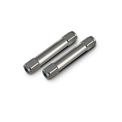
also might look like
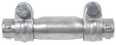
sorry, I didn't call it by its given name - tie rod sleeves.... or put another way the thingamajing that holds the whatsit together so you can go vroom vroom... normally made of steel, black

seriously, the stops are on the spindles - and normally speaking, you'd be able to turn sharper to the right than the left because the steering box impedes turning as far to the left
Last edited by SuperBuickGuy; 03-30-2013 at 10:58 AM.
03-31-2013, 08:57 AM
#26
Heel & Toe
Thread Starter
Member Since: Feb 2013
Posts: 18
Likes: 0
Received 0 Likes
on
0 Posts
also might look like
sorry, I didn't call it by its given name - tie rod sleeves.... or put another way the thingamajing that holds the whatsit together so you can go vroom vroom... normally made of steel, black
seriously, the stops are on the spindles - and normally speaking, you'd be able to turn sharper to the right than the left because the steering box impedes turning as far to the left
03-31-2013, 11:04 AM
#27
Melting Slicks
03-31-2013, 11:16 AM
#28


Back when I was single and not a homeowner and had more free time, in an attempt to make sure everything was centered and straight, I measured everything in the steering. I found that the power steering control valve needed to be rotated a few turns on the center link to make the tie rod ends equal.
 05-02-2013, 07:56 PM
#30
Heel & Toe
Thread Starter
Member Since: Feb 2013
Posts: 18
Likes: 0
Received 0 Likes
on
0 Posts
I got them with the spring kit from VB&P. But they are both the same length so that should not be an issue.
05-02-2013, 09:50 PM
#31
Burning Brakes

Member Since: Sep 2008
Location: Naperville Illinois
Posts: 805
Likes: 0
Received 5 Likes
on
4 Posts
Here is another thought. I would assume there is more than one pitman am that would fit that Saginaw gear box. Any way to tell if mine is the right one? I don't have anything to compare it to.I mean right now the simple fix is a pitman arm that is shaped a little differently that would align with the control valve.
05-03-2013, 06:18 AM
#32
Le Mans Master


Member Since: Jul 2000
Location: Saginaw Michigan
Posts: 6,001
Likes: 0
Received 98 Likes
on
81 Posts

The castings are slightly different.
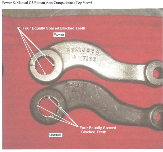
The manual steering pitman arm has the numbers 3829452 forged or cast on the arm. It was used from 1963 through 1976 on manual steering Corvettes.
The power steering pitman arm had the numbers 3741383 usually with an "A" or "B" suffix. It was used on 1963 through 1982 Corvettes with power steering. It was also used on full size Chevrolet passenger cars from 1958 through 1964 with power steering.
Jim
 12-21-2017, 05:49 PM
#34
Melting Slicks

Scooter53 do your indicators cancel correctly from both left and right turns? Why I ask is that this will give some clue as to whether all is well with the alinement of all the steering components. I don't see any mention of you removing the horn button to check where the line is on the end of the steering shaft (it looks like a chisel mark)
This mark should be at 12 o'clock with the steering shaft halfway between full lock left and right. The steering box input shaft should have the flat where the flexible coupling attaches facing upward and the pitman arm should be facing straight ahead. If any one of these conditions is not met than someone has assembled things incorrectly.
What often happens is someone screws up the above and then gets the steering straight by adjusting the tie rods.