700R4 Transmission Rebuild (Lots of Pics Inside, Maybe Too Many for Dial-Up)
 05-19-2008, 08:31 PM
#21
Burning Brakes

Thread Starter
So what are the purple scratches on the rear shaft that are where the speed sensor is located? What about the other scratches?
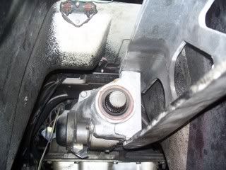
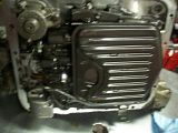
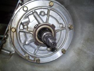
1. Tailhousing extension (need to remove speed sensor to get one of the 4 bolts outs)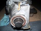
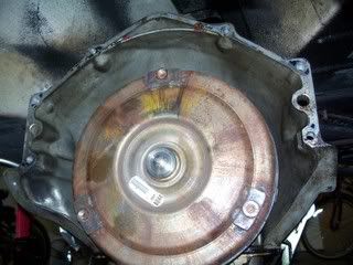
2. Top of bellhousing with build info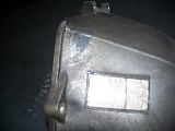
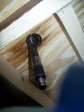
3. What is this hollow rubber tube on top of the bellhousing, some sort of pressure release?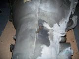
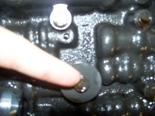
4. Purple scratches on rear shaft where speed sensor should go
5. More scratches on shaft.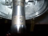
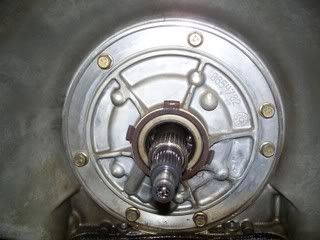
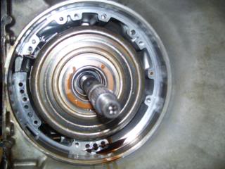
6. Front view w/out TC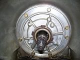
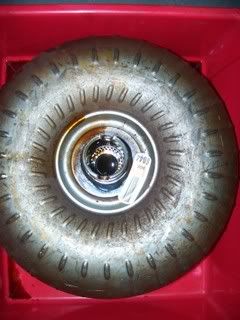
7. Big Stock Converter
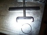
8. Governor cap had no rubber seal! What's with that? It is the first time this tranny has been opened since build day.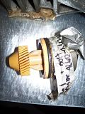
9. Pins you need to slide the bellhousing off of.
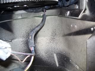
10. Cooler Lines (13mm or � inch flare wrench)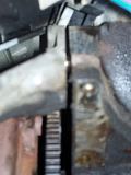
11. Front with converter.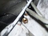
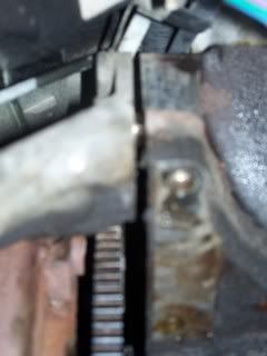
12. Out underneath the car – damnit doesn’t fit! Put on MDF and slid out underneath passenger side rail.
13. Empty void where trans used to be.
14. Ditto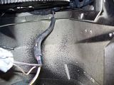
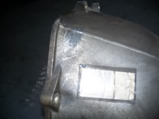
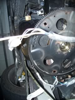
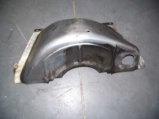
15. Bellhousing dust cover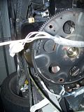
16. Driveshaft (has yellow paint dot for alignment/balance, lighter than I imagined and SPICER along with Ujoint).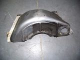
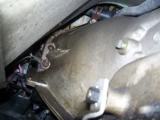
17. C-beam and rear of tranny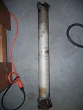
18. Bellhousing Bolts (the lower left has three wires underneath a nut and then a nut onto a bolt behind that – need deep socket 14 mm or 9/16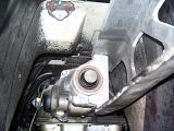
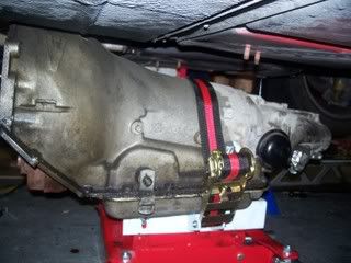
19. Tranny supported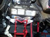
20. Side View again of trans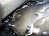
1. Tailhousing extension (need to remove speed sensor to get one of the 4 bolts outs)

2. Top of bellhousing with build info
3. What is this hollow rubber tube on top of the bellhousing, some sort of pressure release?

4. Purple scratches on rear shaft where speed sensor should go
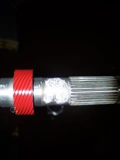
5. More scratches on shaft.

6. Front view w/out TC
7. Big Stock Converter
8. Governor cap had no rubber seal! What's with that? It is the first time this tranny has been opened since build day.

9. Pins you need to slide the bellhousing off of.

10. Cooler Lines (13mm or � inch flare wrench)
11. Front with converter.

12. Out underneath the car – damnit doesn’t fit! Put on MDF and slid out underneath passenger side rail.
13. Empty void where trans used to be.
14. Ditto
15. Bellhousing dust cover
16. Driveshaft (has yellow paint dot for alignment/balance, lighter than I imagined and SPICER along with Ujoint).
17. C-beam and rear of tranny

18. Bellhousing Bolts (the lower left has three wires underneath a nut and then a nut onto a bolt behind that – need deep socket 14 mm or 9/16
19. Tranny supported

20. Side View again of trans
Last edited by janarvae; 06-20-2008 at 12:58 PM.
 05-19-2008, 09:19 PM
#22
Safety Car


Great details and awesome pictures. This is what this forum is about.
This will help other forum members in the future.
Also, very impressive that you will do the rebuild. The Tranny is the 1 thing I haven't even thought of trying to rebuild myself, and I do everything on my Vette !
Vic
This will help other forum members in the future.
Also, very impressive that you will do the rebuild. The Tranny is the 1 thing I haven't even thought of trying to rebuild myself, and I do everything on my Vette !
Vic
05-19-2008, 09:32 PM
#23
Burning Brakes
Thread Starter
Great details and awesome pictures. This is what this forum is about.
This will help other forum members in the future.
Also, very impressive that you will do the rebuild. The Tranny is the 1 thing I haven't even thought of trying to rebuild myself, and I do everything on my Vette !
Vic
This will help other forum members in the future.
Also, very impressive that you will do the rebuild. The Tranny is the 1 thing I haven't even thought of trying to rebuild myself, and I do everything on my Vette !
Vic
I've been taking a LOT of pictures for that exact reason. I don't really need them, but I figure it could help someone else later somehow. I also have all these pictures in very large dimensions, but put them smaller for space issues. If anyone needs them, just visit my photobucket album at http://s290.photobucket.com/albums/l...ion%20Rebuild/. And thanks again for the driveshaft advice and transmission removal write-up.
-I just realized the picture labels are one off, but its a little more work than I want to do at this moment, maybe another day.....
Jonathan
05-19-2008, 10:42 PM
#24
Racer

Member Since: May 2006
Location: Pace Florida
Posts: 283
Likes: 0
Received 0 Likes
on
0 Posts
Great details and awesome pictures. This is what this forum is about.
This will help other forum members in the future.
Also, very impressive that you will do the rebuild. The Tranny is the 1 thing I haven't even thought of trying to rebuild myself, and I do everything on my Vette !
Vic
This will help other forum members in the future.
Also, very impressive that you will do the rebuild. The Tranny is the 1 thing I haven't even thought of trying to rebuild myself, and I do everything on my Vette !
Vic
05-20-2008, 12:57 AM
#25

I did mine and it is running really good. I relied upon this forum, Pete K's advice to me and others, a bit by bit video of my exact transmission. . . I could not go wrong!!!!
THANKS GUYS FOR SAVING ME A TON OF DOUGH!!!!
THANKS GUYS FOR SAVING ME A TON OF DOUGH!!!!
05-24-2008, 10:29 AM
#26
Burning Brakes
Thread Starter
I have the valve body disassembled, pump, input shaft, and front sungear out as of yet. I had to go out last night to get a pair of snap ring pliers with a 45* tip to them to make the front planetary snap ring easier to get out. My $10 crafstman external/internal snap-ring pliers worked great for removing other pistons and snap rings so far, but it kept slipping on this particular one. I picked up a set of two craftsman - one external, one internal - for $20 and they come with 45*, 90*, and straight tips.
I have TONS of pictures of everything from wiring harness removal to checkball locations to pump removal so far. There are so many and I upload all of them to my photobucket, but go through and pick out the best/fewest to be gentle on those with slower internet/the forum's servers. So I'll try and have some up tonight if not tomorrow.
DOES ANYONE KNOW WHERE TO FIND A TRANS PAN SQUARE MAGNET? I found out that when the trans pan fluid and filter were changed at 20,000 miles, whatever idiots did the work lost the magnet!! The local dealer wants $12 and it won't be here until next week. I guess I can always drop the pan again next week to put it in, but I really want to get it in this weekend so I'm not wasting fluid. I did pick up some ceramic magnets last night for when I drill the valve body for the trans-go shift kit. Can I use these or will they crack or something under heat? They rubbed off all sorts of black stuff on my hands when I removed them from the packaging.
Oh, and all the local trans shops won't jetwash the case and pan unless I'm getting my transmission rebuilt with them! Guess I'll use my pressure-washer, brake-kleen, and use compressed air on all of it. I can do the c-beam at the same time I guess.
Jonathan
Last edited by janarvae; 05-24-2008 at 10:31 AM.
05-26-2008, 11:50 AM
#27
Burning Brakes
Thread Starter
Here are the pics of disassembly. I currently have only the case exterior and interior, bellhousing dust cover, separator plate, and pan cleaned. Had to pay $12 to the chevy dealer for the pan magnet which I get Wed. Got to also order a new 17 tooth, red speedo drive gear bc I chipped mine trying to get it off and still haven't gotten it off!! A tip I got from Dana at ProBuilt is to soak the separator plate, valve body, and pan in almost boiling water with soap overnight and the gaskets come right off. Otherwise they are very brittle and you WILL scratch the surfaces trying to remove the gaskets!
Couldn't get my pressure washer working and used engine degreaser followed by hand cleaning the exterior with mineral spirits in a squirt bottle - worked great for exterior grease! Used brakleen (I guess they discontinued the non-chlorinated form?) for internal and dried with compressed air.
One tip, for disassembly of input shaft, a 2" hole saw will make a nice hole for the the shaft AND drainage with a bucket straight underneath to catch fluid when you take the pan and valve body off. It served two important functions and was worth the trouble of trying to cut sheet metal with a spinning hole saw (ended up scoring and using a punch to make the metal hole, no problem cutting through the 3/4" plywood in my workbench).
Here are the pictures, limited to 25/post so I'll put another post of pics up too. Click to make bigger.
1. Pan
2. Filter
3. Wiring
4. Brackets
5. Wiring Bracket
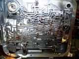
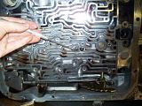
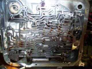
6. Valve Body
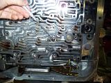
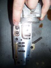
7. Auxilary Valve Body
8-14. Checkball Locations
15. Pump
16. Pump Removed
17. Remove pin before trying to pull out input shaft with band.
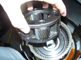
18. Input subassembly
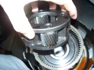
19. What�s left in case (sungears, sungear shell, planetaries, spring retainers, etc. )
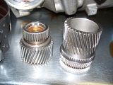
20. Sungear out.
21. Front and Rear sungears.
22. Small snap-ring was PITA until I bought the right 45* curved tips.
23. Front Planetary
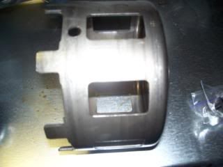
24. Stock sungear shell.
25. Another PITA snap ring. Had to use spring compressor tool, pick, snapring pliers, and patience to get out. Stand the case upright, get on a stepstool, and it�ll make it much easier.
1.
2.
3.
4.
5.
6.
7.
8.
9.
10.
11.
12.
13.
14.
15.
16.
17.
18.
19.
20.
21.
22.
23.
24.
25.
Couldn't get my pressure washer working and used engine degreaser followed by hand cleaning the exterior with mineral spirits in a squirt bottle - worked great for exterior grease! Used brakleen (I guess they discontinued the non-chlorinated form?) for internal and dried with compressed air.
One tip, for disassembly of input shaft, a 2" hole saw will make a nice hole for the the shaft AND drainage with a bucket straight underneath to catch fluid when you take the pan and valve body off. It served two important functions and was worth the trouble of trying to cut sheet metal with a spinning hole saw (ended up scoring and using a punch to make the metal hole, no problem cutting through the 3/4" plywood in my workbench).
Here are the pictures, limited to 25/post so I'll put another post of pics up too. Click to make bigger.
1. Pan
2. Filter
3. Wiring
4. Brackets
5. Wiring Bracket
6. Valve Body
7. Auxilary Valve Body
8-14. Checkball Locations
15. Pump
16. Pump Removed
17. Remove pin before trying to pull out input shaft with band.
18. Input subassembly
19. What�s left in case (sungears, sungear shell, planetaries, spring retainers, etc. )
20. Sungear out.
21. Front and Rear sungears.
22. Small snap-ring was PITA until I bought the right 45* curved tips.
23. Front Planetary
24. Stock sungear shell.
25. Another PITA snap ring. Had to use spring compressor tool, pick, snapring pliers, and patience to get out. Stand the case upright, get on a stepstool, and it�ll make it much easier.
1.

2.

3.

4.

5.

6.
7.
8.
9.
10.

11.

12.

13.

14.

15.
16.
17.
18.
19.
20.
21.

22.

23.
24.
25.
 05-26-2008, 12:01 PM
#28
Burning Brakes
Thread Starter
As promised:
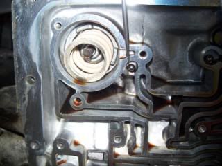
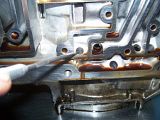
1. Blow 40psi to remove final piston following snap ring removal of spring compressor.
2. Here is the hole to blow into.
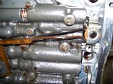
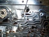
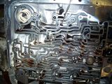
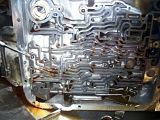
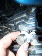
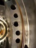
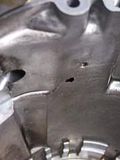
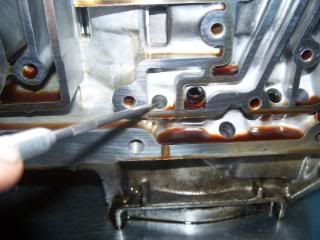
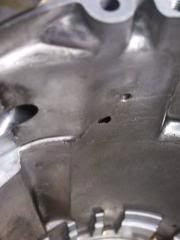
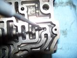
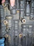
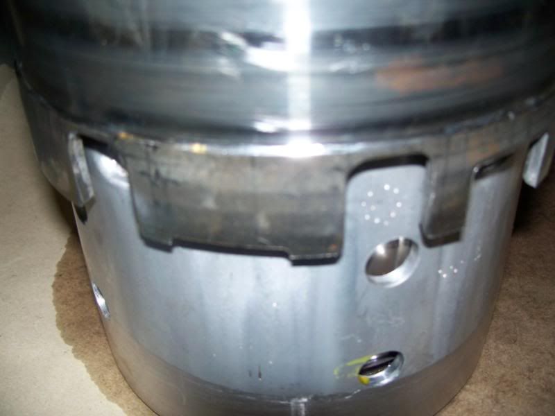
3. Chip in one of the pump holes (is this bad?)
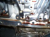
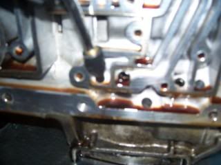
4. The upper hole comes from the 4th and 2nd gear piston, the lower does not look machined or stock, is this a problem?
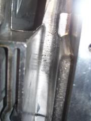
5. Where the shifter linkage to the right of the valve body (with case upright) looks rough too, is this bad?
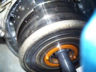
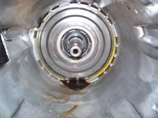
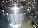
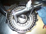
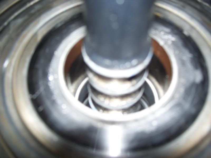
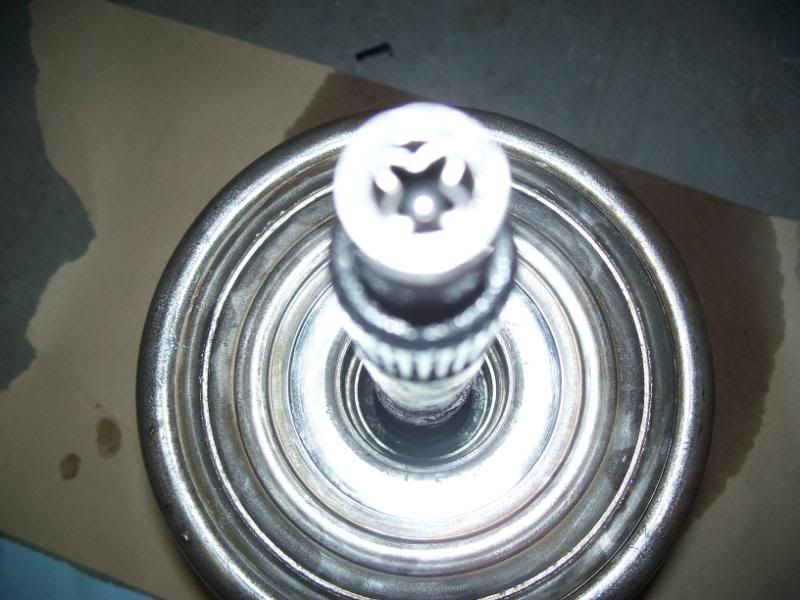
6. Input drum/shaft in hole.
7. View from bottom.
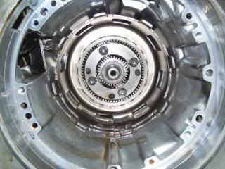
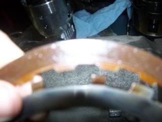
8. Clutches don�t look too bad.
9. Ditto.
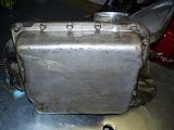
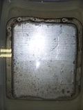
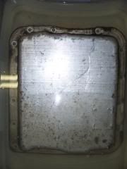
10. Pan Soaking with separator plate underneath it.
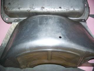
11. Clean bellhousing dust cover and pan.
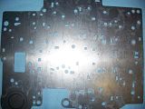
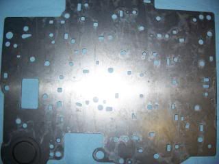
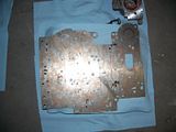
13. Clean separator plate.
I also cleaned the c-beam up nicely but didn�t snap a picture
1.
2.
3.
4.
5.
6.
7.
8.
9.
10.
11.
12.
1. Blow 40psi to remove final piston following snap ring removal of spring compressor.
2. Here is the hole to blow into.
3. Chip in one of the pump holes (is this bad?)
4. The upper hole comes from the 4th and 2nd gear piston, the lower does not look machined or stock, is this a problem?
5. Where the shifter linkage to the right of the valve body (with case upright) looks rough too, is this bad?
6. Input drum/shaft in hole.
7. View from bottom.
8. Clutches don�t look too bad.
9. Ditto.
10. Pan Soaking with separator plate underneath it.
11. Clean bellhousing dust cover and pan.
13. Clean separator plate.
I also cleaned the c-beam up nicely but didn�t snap a picture
1.
2.
3.

4.
5.
6.

7.

8.

9.
10.
11.
12.


 06-18-2008, 07:58 PM
#31
Burning Brakes
Thread Starter
Well, I'm almost done!! It'll definitely be going in this weekend. I've rebuilt and/or upgraded every subassembly, and am in the process of pressing in the final bushings in the sun gears, case, and extension housing. The front pump (with new PR/TV Boost valve, seals, new stator shaft, pump insides), reverse and forward input drums, reverse roller assembly (with new roller), modified valve body, modified separator plate, and I'm probably forgetting one or two subassemblies, but will correct myself when I go down to the garage and get my camera.
Jonathan
06-18-2008, 09:36 PM
#32
Burning Brakes
Thread Starter
1. Aux. Valve Body with cleaned valves, new pin and piston, and a new spacer with smaller oil hole and new spring IIRC. Use vaseline to hold in new checkball on the flat side (my '91 had a check ball retainer that needed to be popped out with a pick). Use carb cleaner, air, brake cleaner, air on all valves. Lubrication with tranny oil just make reinstallation messier. Other parts though SHOULD be lubricated with tranny oil, such as clutches, 2-4 band, forward sprag, rear roller assembly, pump inner workings, stator shaft for pressing in new one, etc.
*Before touching the valve body, you may have some of the paper gasket stuck to the face. Get boiling water, dish soap, and a large plastic container, fill and add valve body. Gasket slides right off. Do this with the separator plate also. Use a sharp razor blade if any remains. Be careful not to scratch the face and go over with a large 12 in bastard file over the entire surface to take off any high spots before your final cleaning and reinstallation of valves. You may not be able to see high spots, but they are there.
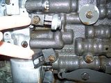
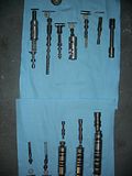
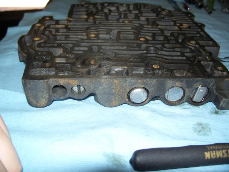
2. Valve Body with 5 valves out for cleaning.
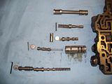
3. 3 Valves on other side (notice that the valve bushings on these must be oriented properly for the roll pin to seat)
4. More pictures of #2. You need a GM oil pressure sender socket (got mine from NAPA) to remove the regulator seen still attached to the valve body here. Test with rubber-tipped blow nozzle at 100psi - the lowest pressure in a running tranny is ~75psi in Neutral (as told by Dana at ProBuilt), so why test it any lower? Mine was still good - so much so that it blew the rubber tip off of my blow handle instead of breaking the seal!! A little oil coming out of the front is normal as there is a diaphragm in there.

5. 3 Large Valves and Bushings
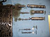
6. All of the valves organized and off the worktable so I can clean the valve body (used Brakleen and compressed air)
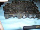
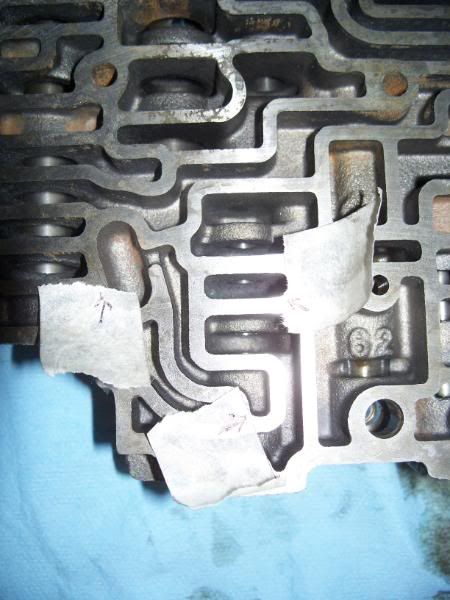
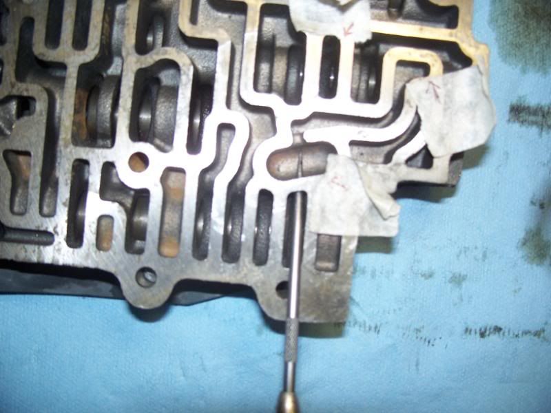
7. Locations of the 3 hole modifications. Keep a magnet close - you will magnetize the valve body and drill. Blow out and clean WELL with carb cleaner.
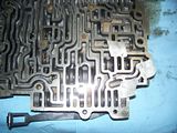
8. Duplicate of 7
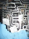
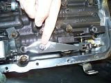
9. A view of the pick going through the wall of one cavity into the pool/bean. For all these holes make a dink first with a punch and set the drill bit on that. GO SLOWLY!!

10. Second hole drilled into the valve bore (go slowly or you will nick the bottom of the bore and have to go in there with a small file so the bushing holding the valve will slide freely)
11. Third hole that goes through a rectangular cavity through the bottom of the valve body. Notice the pick is sticking out of the bottom.
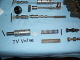
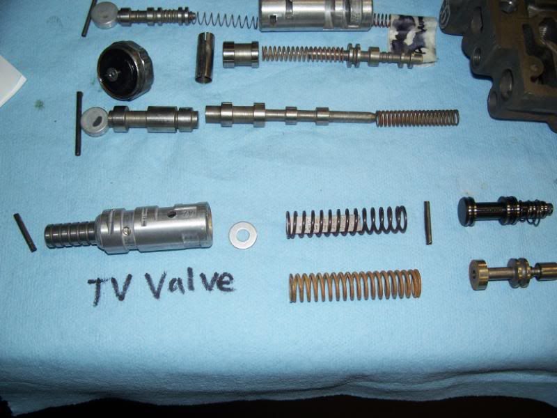
12. New TV valve next to old TV valve setup. I had some trouble with this because the '91 is apparently oriented differently than the TransGo instructions. I contacted Dana at ProBuilt automatics and he confirmed my suspicions. I'm glad I took lots of pics for reference!
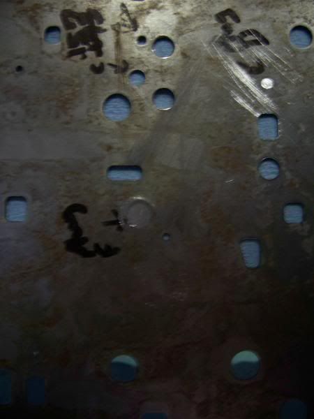
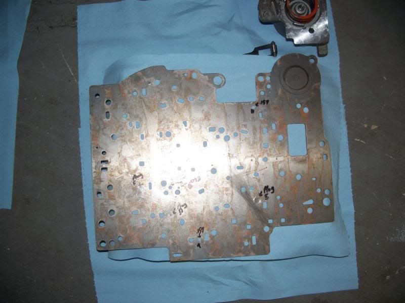
13. Separator plate mod - required me to enlarge some holes and plug 3 others. My duct steel covered work bench was denting upon impact and I had to use my concrete floor to properly seat the plugs. DO NOT bend the separator plate when hammering in the plugs. File both sides of each plug level and remove any burrs from drilling the holes.
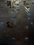
14. Same as 13.
Now to organize the next subassembly...
Jonathan
*Before touching the valve body, you may have some of the paper gasket stuck to the face. Get boiling water, dish soap, and a large plastic container, fill and add valve body. Gasket slides right off. Do this with the separator plate also. Use a sharp razor blade if any remains. Be careful not to scratch the face and go over with a large 12 in bastard file over the entire surface to take off any high spots before your final cleaning and reinstallation of valves. You may not be able to see high spots, but they are there.
2. Valve Body with 5 valves out for cleaning.

3. 3 Valves on other side (notice that the valve bushings on these must be oriented properly for the roll pin to seat)
4. More pictures of #2. You need a GM oil pressure sender socket (got mine from NAPA) to remove the regulator seen still attached to the valve body here. Test with rubber-tipped blow nozzle at 100psi - the lowest pressure in a running tranny is ~75psi in Neutral (as told by Dana at ProBuilt), so why test it any lower? Mine was still good - so much so that it blew the rubber tip off of my blow handle instead of breaking the seal!! A little oil coming out of the front is normal as there is a diaphragm in there.
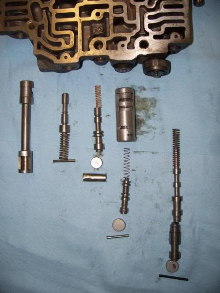
5. 3 Large Valves and Bushings
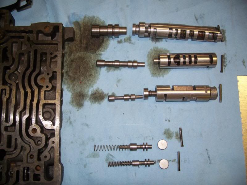
6. All of the valves organized and off the worktable so I can clean the valve body (used Brakleen and compressed air)

7. Locations of the 3 hole modifications. Keep a magnet close - you will magnetize the valve body and drill. Blow out and clean WELL with carb cleaner.

8. Duplicate of 7
9. A view of the pick going through the wall of one cavity into the pool/bean. For all these holes make a dink first with a punch and set the drill bit on that. GO SLOWLY!!
10. Second hole drilled into the valve bore (go slowly or you will nick the bottom of the bore and have to go in there with a small file so the bushing holding the valve will slide freely)

11. Third hole that goes through a rectangular cavity through the bottom of the valve body. Notice the pick is sticking out of the bottom.

12. New TV valve next to old TV valve setup. I had some trouble with this because the '91 is apparently oriented differently than the TransGo instructions. I contacted Dana at ProBuilt automatics and he confirmed my suspicions. I'm glad I took lots of pics for reference!
13. Separator plate mod - required me to enlarge some holes and plug 3 others. My duct steel covered work bench was denting upon impact and I had to use my concrete floor to properly seat the plugs. DO NOT bend the separator plate when hammering in the plugs. File both sides of each plug level and remove any burrs from drilling the holes.
14. Same as 13.
Now to organize the next subassembly...
Jonathan
Last edited by janarvae; 06-20-2008 at 10:30 PM.
06-18-2008, 10:17 PM
#33
Burning Brakes
Thread Starter
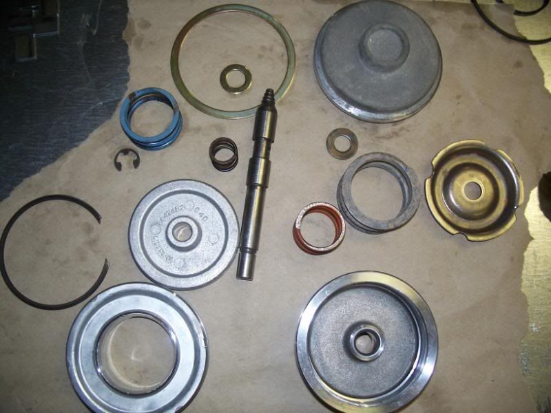
Here are pics of the 1-2 accumulator assembly and front pump rebuild.
1. 1-2 accumulator rebuilt. New spring on bottom of new piston, new pin (use red loctite on this and aux. valve body pin).
2. Piston and old spring.

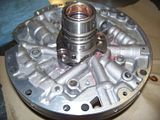
3. Pump disassembled.
4. Old pump vane, rotor, (slide not pictured).

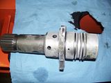
5. Pre-rebuild stator shaft. Again, use a 12 in. bastard file to knock off any high spots on the surface.
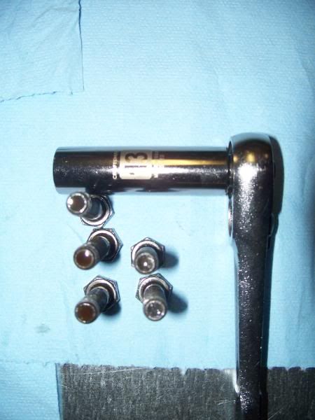
6. 2 Springs holding pump slide in (the large outer ring with tooth). Replace the two springs, removed with screwdriver (be careful removing - it can hit you)
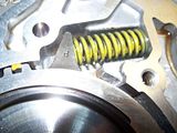
7. Picture of pin location - DONT lose the tiny red/orange spring underneath the pin. Rebuild kit included new pin, but no spring.
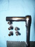
8. 5 bolts with socket used to take off. USE AIR TOOLS TO REMOVE BOLTS (same for stator shaft - use T27 bit)!!
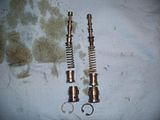
9. Boost valve and pressure regulator valve, new vs. old. Make sure snap ring fits in proper groove when reinstalling and have the flatter/sharper side facing you upon reinstallation. (Not pictures is torque convertor clutch solenoid). If you need a pic, check out my photobucket at http://s290.photobucket.com/albums/l...ion%20Rebuild/.
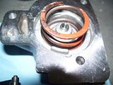
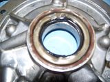
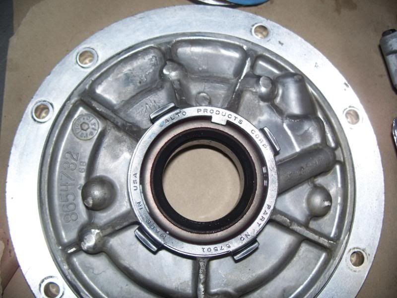
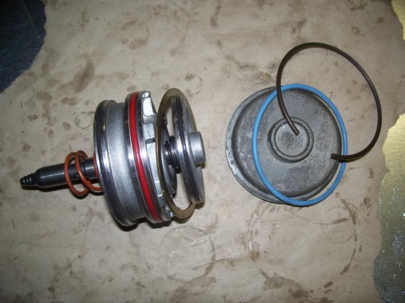
10. Front pump seal - what a SOB!! Use a chisel and tap all the way around to get under lip. Continue until seal comes off. Replace seal retainer clip also (pictured in #10 over new seal).
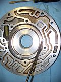
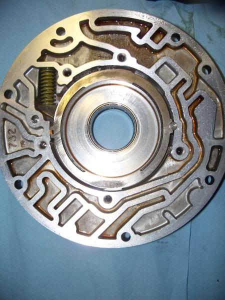
11. Clean any old paint left by the old seal very carefully with a razor blade. Use 600 grit sandpaper and smooth out any nicks you may have created in the inside. If you look closely, you can see I took a dremel and removed a lot of casting imperfections in the outer front pump half. I used the conical green silicone carbide bit ($2 at HomeDepot, came with the Dremel). Pretty, huh? Use a flat 2x4 or 4x4 and tap with mallet. Tap new seal in until it seats flush and then clip new retainer over.

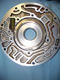
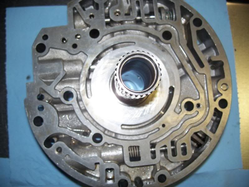
12. Stator pump half ready to go in oven to get hot while new stator shaft has been in freezer for a day. Makes pressing it in easier.
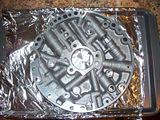
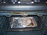
13. In the oven. REMOVE the pressure relief checkball and SPRING before putting in oven. DO NOT put in oven with any valves or springs in - you can leave the two tiny checkballs in there though. Or pop them out of their retainers gently with a pick to the back of the ball. Then reinsert and bend back the retaining metal if you bent it open when extruding the *****. I put in the oven for 20 min. at 250*F.
14. New better stator shaft out of freezer, ready to be pressed in. Use some sort of lube when pressing in (I used tranny fluid).
15. Pin that aligns the bolt holes of the stator pump half and stator shaft properly. Replacement stator shafts have a oblong hole to accomodate a different GM transmission pin.
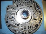
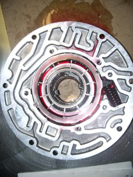
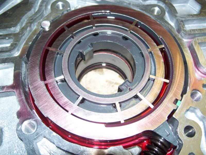
16. Pressed in.
17.New vane, slide, rotor, etc and lubed with LOTS of tranny fluid - DONT forget the small teflon round stick and green rectangle (the old one was orange). Also put in the new pin, springs (PITA), and washer covered by metal retaining ring on the underside of the rotor/vane assembly. Hold these in place with vaseline. Vaseline is your best friend (besides snap-ring pliers) in this rebuild!!!
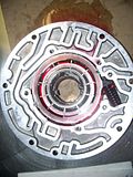
18. Another pic of new vanes, etc.
1. 1-2 accumulator rebuilt. New spring on bottom of new piston, new pin (use red loctite on this and aux. valve body pin).

2. Piston and old spring.
3. Pump disassembled.
4. Old pump vane, rotor, (slide not pictured).
5. Pre-rebuild stator shaft. Again, use a 12 in. bastard file to knock off any high spots on the surface.
6. 2 Springs holding pump slide in (the large outer ring with tooth). Replace the two springs, removed with screwdriver (be careful removing - it can hit you)
7. Picture of pin location - DONT lose the tiny red/orange spring underneath the pin. Rebuild kit included new pin, but no spring.

8. 5 bolts with socket used to take off. USE AIR TOOLS TO REMOVE BOLTS (same for stator shaft - use T27 bit)!!
9. Boost valve and pressure regulator valve, new vs. old. Make sure snap ring fits in proper groove when reinstalling and have the flatter/sharper side facing you upon reinstallation. (Not pictures is torque convertor clutch solenoid). If you need a pic, check out my photobucket at http://s290.photobucket.com/albums/l...ion%20Rebuild/.

10. Front pump seal - what a SOB!! Use a chisel and tap all the way around to get under lip. Continue until seal comes off. Replace seal retainer clip also (pictured in #10 over new seal).

11. Clean any old paint left by the old seal very carefully with a razor blade. Use 600 grit sandpaper and smooth out any nicks you may have created in the inside. If you look closely, you can see I took a dremel and removed a lot of casting imperfections in the outer front pump half. I used the conical green silicone carbide bit ($2 at HomeDepot, came with the Dremel). Pretty, huh? Use a flat 2x4 or 4x4 and tap with mallet. Tap new seal in until it seats flush and then clip new retainer over.
12. Stator pump half ready to go in oven to get hot while new stator shaft has been in freezer for a day. Makes pressing it in easier.

13. In the oven. REMOVE the pressure relief checkball and SPRING before putting in oven. DO NOT put in oven with any valves or springs in - you can leave the two tiny checkballs in there though. Or pop them out of their retainers gently with a pick to the back of the ball. Then reinsert and bend back the retaining metal if you bent it open when extruding the *****. I put in the oven for 20 min. at 250*F.

14. New better stator shaft out of freezer, ready to be pressed in. Use some sort of lube when pressing in (I used tranny fluid).

15. Pin that aligns the bolt holes of the stator pump half and stator shaft properly. Replacement stator shafts have a oblong hole to accomodate a different GM transmission pin.

16. Pressed in.

17.New vane, slide, rotor, etc and lubed with LOTS of tranny fluid - DONT forget the small teflon round stick and green rectangle (the old one was orange). Also put in the new pin, springs (PITA), and washer covered by metal retaining ring on the underside of the rotor/vane assembly. Hold these in place with vaseline. Vaseline is your best friend (besides snap-ring pliers) in this rebuild!!!
18. Another pic of new vanes, etc.
Last edited by janarvae; 06-18-2008 at 10:22 PM.
06-18-2008, 10:50 PM
#34
Drifting

Member Since: Dec 2005
Location: High Ridge Missouri
Posts: 1,313
Likes: 0
Received 2 Likes
on
2 Posts

Very nice write-up. Thanks for putting up all the pics too. You are definitely doing a more thorough job than I've ever done on a rebuild. Keep up the good work and keep us posted.
06-19-2008, 09:55 AM
#35
Race Director

You can never have too many images to go along with a rebuild.
So; what airplane model are you building that is sitting on the upper shelf in the corner of your garage?
It looks to be a Gallow's model of a Piper Cub
So; what airplane model are you building that is sitting on the upper shelf in the corner of your garage?
It looks to be a Gallow's model of a Piper Cub
06-19-2008, 01:41 PM
#36
Burning Brakes
Thread Starter
As to the airplane, that is JimiHendrix's garage, not mine. I'll be posting more pics tonight because I have a 3 day weekend and plan on having the tranny back in in the next two days.
Jonathan
06-20-2008, 11:37 AM
#38
Burning Brakes
Thread Starter
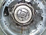
1. Spring retainer being compressed so snap ring can be removed.
2. Snap ring pictured at end of pick.
3. A more complete view of the universal spring compressor apparatus
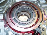
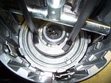
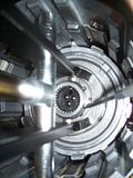
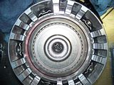
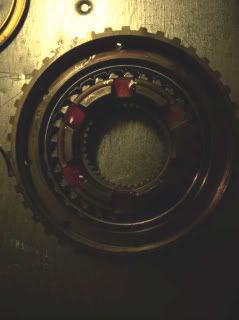
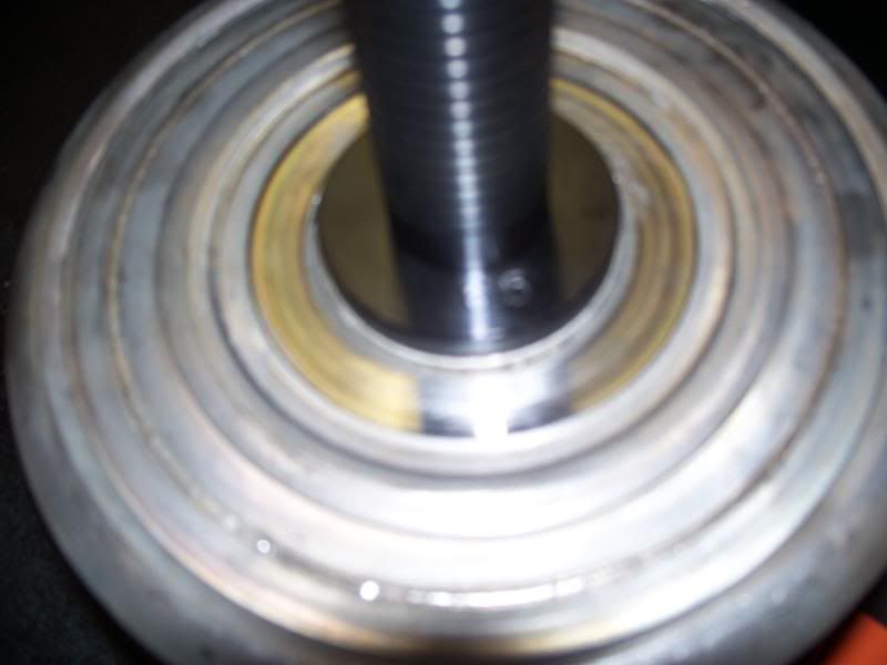
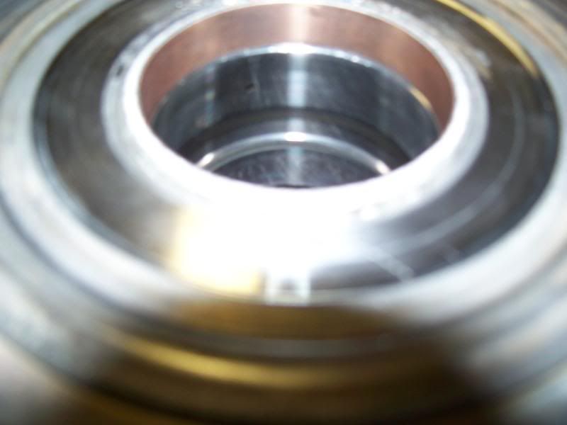
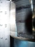
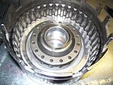
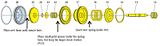
4. Input sprag, outer and inner races. The input sprag should be replaced if the tranny has more than 40,000 miles at the time of the rebuild (as recommended by Paul Zanck of instructional video). I replaced with a Raybestos SKF single cage 29 element design. The outer race had grooves in it when the transmission was new. To replicate that effect (grooves), take 40 grit sandpaper (usually aluminum oxide) and place the outer race on its side and roll along benchtop while holding sandpaper inside. The inner race should be perfectly smooth. On any surface where you must sand to remove burrs, etc. in this transmission, always do so in a circular (to the orientation of the part) manner. DO NOT go up and down! Lube the sprag and assembly with plenty of tranny fluid (you don't want it to start life dry). Also, if you put the input sprag in upside down, it will ruin the overrun clutches - you will realize you did this if you have NO overdrive!! With it assembled (done by turning the sprag into the assembly), you should be able to hold the larger outer race in your left hand, and the inner race part should turn freely clockwise and lock counterclockwise.
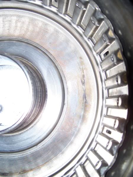
5. Click on this picture to make larger...It shows the sprag properly inside both the inner and outer races/parts.

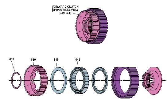
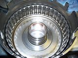
6. Here is a blown-up image of the sprag assembly. Grab the larger toothed part (which comes into contact with the input sprag, purple) with your left hand and, spin the smaller toothed ring (pink) in your right hand, it should only spin clockwise (with the purple part stationary) and lock counter-clockwise.

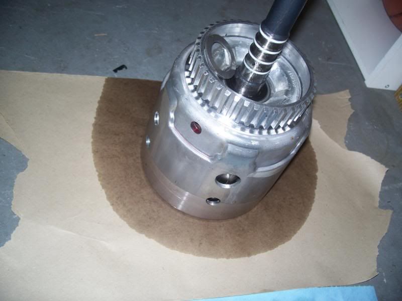
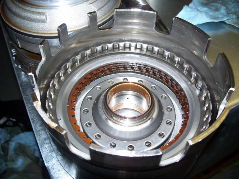
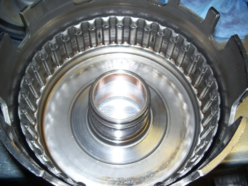
7. Input drum with overrun/engine-braking piston, spring retainer, snap ring, 2 overrun steels, 2 overrun clutches installed and sprag assembly installed. The sprag assembly is installed upside down.
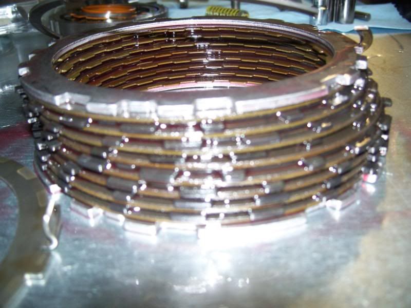
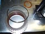
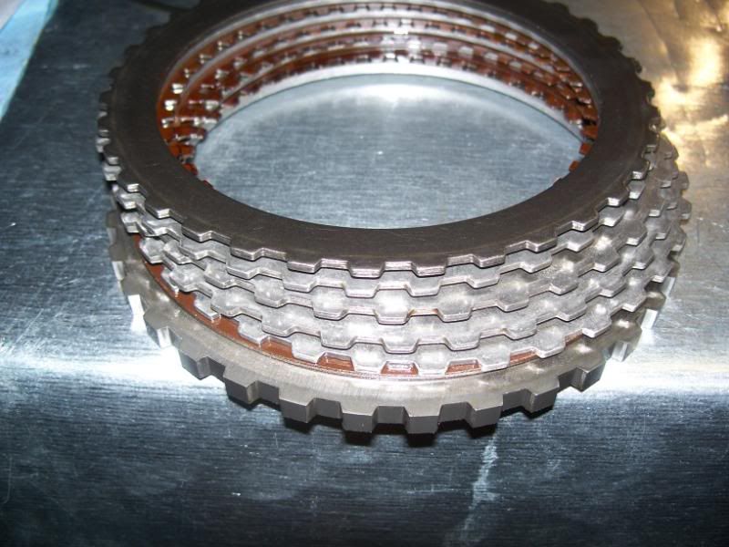
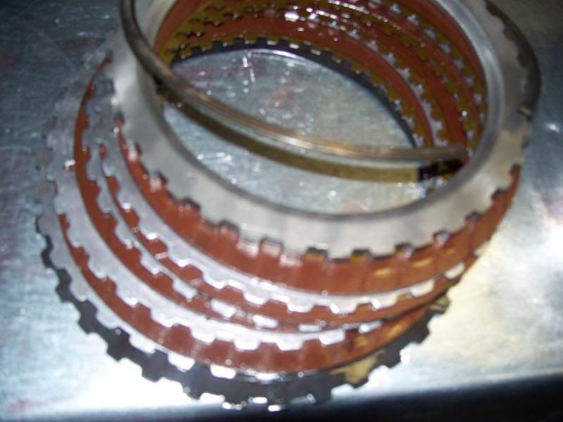
8. Forward clutches and steels. Notice the two new pressure plates on top and bottom. This is the modified 3-4 clutch pack with 8 0.080 Borg-Warner High Energy clutches. The steels are 0.060 and 0.080. A new snap ring is also included in Dana's ProBuilt rebuild kit,

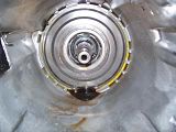
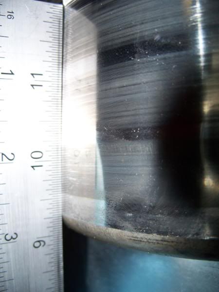
9. Rear bushing on reverse input drum removed, take a chisel and try and tap it so where the bushing clips together like a puzzle piece will cave in. If not, just hit it hard enough that you finally break that puzzle piece joint. I scratched where the thrust washer rides in the process. Took a dremel to it and smoothed out any high spots. Then went in a CIRCULAR motion with 600 grit sandpaper. Turned out good.
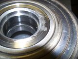
10. Bushing removed - see how much I had to mess it up to remove it? Then guess what happened, I installed the new one in backwards and had to remove that one too!!!! When you install it, the inner bevel must be facing you towards the outside. Man was that fun..

11. Pressed in the 2nd new one correctly with my 20 ton press and special bushing adapter.
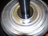
12. The new bushing should sit on the ledge inside of the hole - you will feel notable resistance when you hit that ledge will pressing it in. STOP when you feel that. Again, the bevel on the inside must face you.

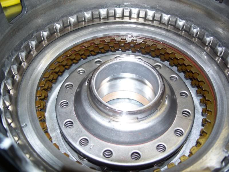
13. Finished forward input drum with 4 new seals on shaft, new HD checkball and retainer at end of shaft (not pictured), new o-ring at top of shaft, clutches pressure tested at 100 PSI. Refer to the Paul Zanck video for what holes to block and where to put your rubber-tipped blow nozzle. Dana at ProBuilt explained that testing at 100 PSI allows the clutches to hold vacuum longer and any wrongly installed pistons/o-rings will be much more evident. Mine was perfect and even the clutch-snap-ring clearance were good with the modified 3-4 clutch setup.

In my next post, I will show the reverse input drum rebuild and it installed over the forward input drum.
Jonathan

2. Snap ring pictured at end of pick.
3. A more complete view of the universal spring compressor apparatus

4. Input sprag, outer and inner races. The input sprag should be replaced if the tranny has more than 40,000 miles at the time of the rebuild (as recommended by Paul Zanck of instructional video). I replaced with a Raybestos SKF single cage 29 element design. The outer race had grooves in it when the transmission was new. To replicate that effect (grooves), take 40 grit sandpaper (usually aluminum oxide) and place the outer race on its side and roll along benchtop while holding sandpaper inside. The inner race should be perfectly smooth. On any surface where you must sand to remove burrs, etc. in this transmission, always do so in a circular (to the orientation of the part) manner. DO NOT go up and down! Lube the sprag and assembly with plenty of tranny fluid (you don't want it to start life dry). Also, if you put the input sprag in upside down, it will ruin the overrun clutches - you will realize you did this if you have NO overdrive!! With it assembled (done by turning the sprag into the assembly), you should be able to hold the larger outer race in your left hand, and the inner race part should turn freely clockwise and lock counterclockwise.

5. Click on this picture to make larger...It shows the sprag properly inside both the inner and outer races/parts.
6. Here is a blown-up image of the sprag assembly. Grab the larger toothed part (which comes into contact with the input sprag, purple) with your left hand and, spin the smaller toothed ring (pink) in your right hand, it should only spin clockwise (with the purple part stationary) and lock counter-clockwise.
7. Input drum with overrun/engine-braking piston, spring retainer, snap ring, 2 overrun steels, 2 overrun clutches installed and sprag assembly installed. The sprag assembly is installed upside down.

8. Forward clutches and steels. Notice the two new pressure plates on top and bottom. This is the modified 3-4 clutch pack with 8 0.080 Borg-Warner High Energy clutches. The steels are 0.060 and 0.080. A new snap ring is also included in Dana's ProBuilt rebuild kit,
9. Rear bushing on reverse input drum removed, take a chisel and try and tap it so where the bushing clips together like a puzzle piece will cave in. If not, just hit it hard enough that you finally break that puzzle piece joint. I scratched where the thrust washer rides in the process. Took a dremel to it and smoothed out any high spots. Then went in a CIRCULAR motion with 600 grit sandpaper. Turned out good.

10. Bushing removed - see how much I had to mess it up to remove it? Then guess what happened, I installed the new one in backwards and had to remove that one too!!!! When you install it, the inner bevel must be facing you towards the outside. Man was that fun..
11. Pressed in the 2nd new one correctly with my 20 ton press and special bushing adapter.
12. The new bushing should sit on the ledge inside of the hole - you will feel notable resistance when you hit that ledge will pressing it in. STOP when you feel that. Again, the bevel on the inside must face you.
13. Finished forward input drum with 4 new seals on shaft, new HD checkball and retainer at end of shaft (not pictured), new o-ring at top of shaft, clutches pressure tested at 100 PSI. Refer to the Paul Zanck video for what holes to block and where to put your rubber-tipped blow nozzle. Dana at ProBuilt explained that testing at 100 PSI allows the clutches to hold vacuum longer and any wrongly installed pistons/o-rings will be much more evident. Mine was perfect and even the clutch-snap-ring clearance were good with the modified 3-4 clutch setup.
In my next post, I will show the reverse input drum rebuild and it installed over the forward input drum.
Jonathan
Last edited by janarvae; 06-23-2008 at 12:12 AM.
06-20-2008, 12:06 PM
#39
Burning Brakes
Thread Starter
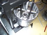
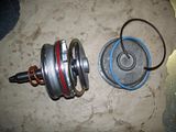
1. Reverse input drum with all old clutches still in it.

2. Compressed the spring retainer to remove the snap ring. I replaced these springs, as well as the forward input drum spring retainer with high-rev springs (shown in blue box with man's face on it in one of my first posts in this thread)

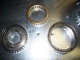
3. Old clutches with belleville plate on bottom that messes up the teeth in the drum on stock applications.

4. Old cluthces with old belleville steel.
5. Compressing the spring retainer again to re-install snap ring.
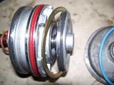
6. Make sure where the 2-4 band rides on the reverse input drum is straight and smooth or replace as the 2-4 band will not have adequate surface to ride on.
7. Cleaned reverse input drum.
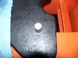
8. Cleaned piston, see the hole? Notice the inner and outer lip seals. Install slowly with lip seal tool (pictured in one of my first posts). Always use vaseline on the o-rings and even on the shaft and drum for a smooth entry of the new piston.
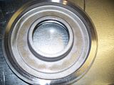
9. See the welds and little ***** of metal from the manufacturing process? This is normal and does not affect performance.

10. New clutches with new waved steel on bottom. Manufacturer recommends installing the top of one of the waves over the hole in the piston.

11. Piston installed and now reinstalling spring retainer.
12. New clutches installed. Make sure the angled side of the top pressure plate faces upwards towards you. Large snap ring also installed.

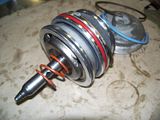
13. Reverse input drum carefully slid on top of forward input drum as to not damage any of the shaft seals.

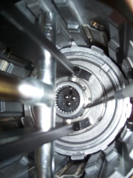
14. Top view of reverse input drum installed over forward input drum. See the new HD checkball and retainer installed at the end of the shaft. Oh, to remove the old checkball and retainer, use a #4 extractor. Then blow out from top and hole in the input shaft to remove any shavings that may be there. Then install new one (comes with ball already installed) with a large drift or curved end of a rod.

15. Reverse input drum installed over forward input drum. When you install it, work the clutches into the teeth of the forward input drum and it should spin freely both ways with a little pressure applied on it with both hands.

2. Compressed the spring retainer to remove the snap ring. I replaced these springs, as well as the forward input drum spring retainer with high-rev springs (shown in blue box with man's face on it in one of my first posts in this thread)

3. Old clutches with belleville plate on bottom that messes up the teeth in the drum on stock applications.
4. Old cluthces with old belleville steel.

5. Compressing the spring retainer again to re-install snap ring.

6. Make sure where the 2-4 band rides on the reverse input drum is straight and smooth or replace as the 2-4 band will not have adequate surface to ride on.
7. Cleaned reverse input drum.
8. Cleaned piston, see the hole? Notice the inner and outer lip seals. Install slowly with lip seal tool (pictured in one of my first posts). Always use vaseline on the o-rings and even on the shaft and drum for a smooth entry of the new piston.

9. See the welds and little ***** of metal from the manufacturing process? This is normal and does not affect performance.
10. New clutches with new waved steel on bottom. Manufacturer recommends installing the top of one of the waves over the hole in the piston.
11. Piston installed and now reinstalling spring retainer.

12. New clutches installed. Make sure the angled side of the top pressure plate faces upwards towards you. Large snap ring also installed.
13. Reverse input drum carefully slid on top of forward input drum as to not damage any of the shaft seals.
14. Top view of reverse input drum installed over forward input drum. See the new HD checkball and retainer installed at the end of the shaft. Oh, to remove the old checkball and retainer, use a #4 extractor. Then blow out from top and hole in the input shaft to remove any shavings that may be there. Then install new one (comes with ball already installed) with a large drift or curved end of a rod.
15. Reverse input drum installed over forward input drum. When you install it, work the clutches into the teeth of the forward input drum and it should spin freely both ways with a little pressure applied on it with both hands.
 06-20-2008, 12:34 PM
#40
Burning Brakes
Thread Starter
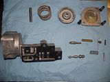
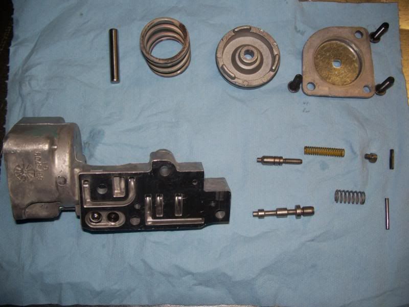
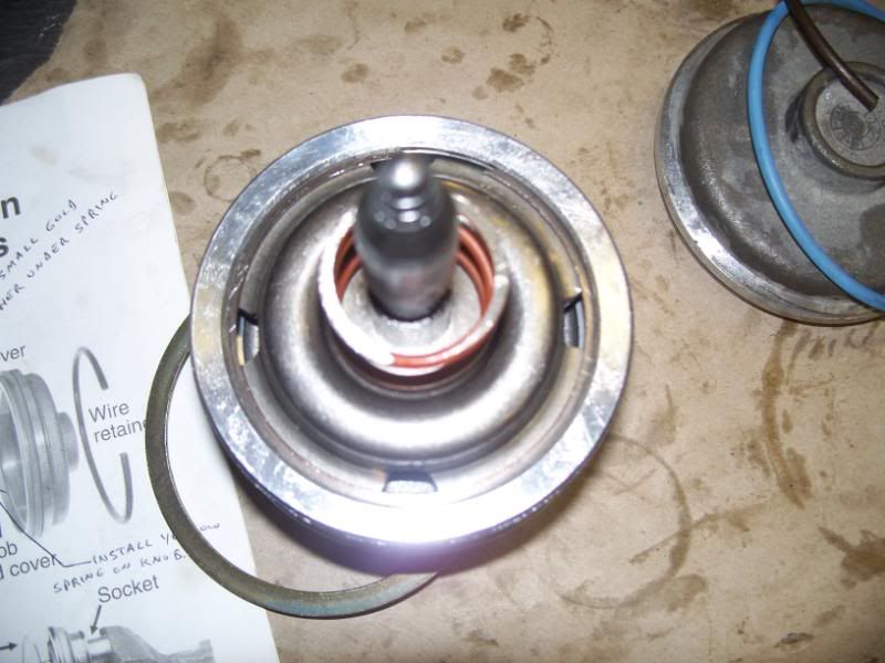
[1. 2-4 servo disassembled and cleaned. To remove the snap ring, use a socket on the rear of the rear of the apply pin (#13 in picture 5).

2. Modified servo cushion spring retainer (#15). Used a large silicone carbide bit on my dremel (the flat circular grinding one included in the grinding accessory kit - its not the cone green one, but the other one) at setting 9. The holes are to allow more oil to exit.

3. Another picture of this modification.

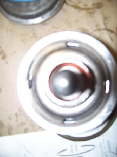
4. From the top.
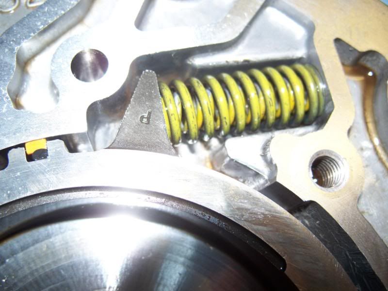
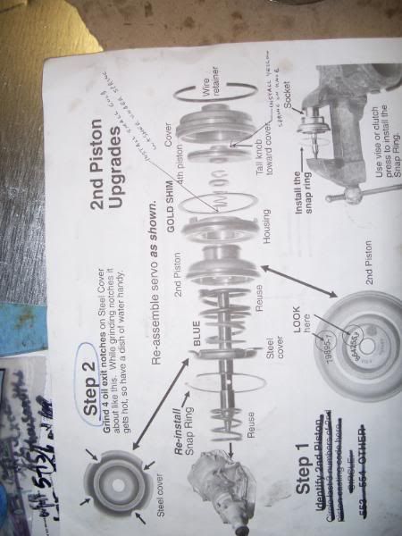
5. Blow-up of 2-4 servo assembly. I forgot to put install yellow coated (may look all black if yellow marking rubbed off) spring over the tall **** of #25 (on the same side as where the arrow points for the large gold spacer).
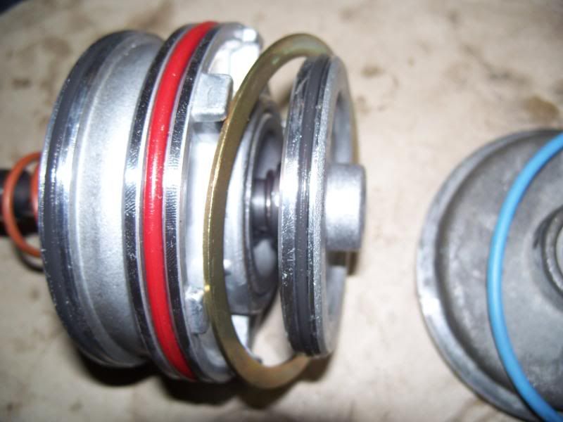
6. Reassembled with new seals, spring installed, new large gold spacer and small gold washer. The red seal will not fill the entire groove - the stock seal did not fill the groove entirely either - I'm guessing its normal.
7. Another picture of it assembled. See the new black seals, large gold spacer, and circlip (like found on brake caliper pin) installed?
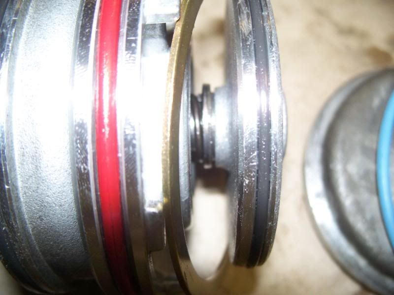
8. Close-up. Install the yellow (or entirely black spring if the yellow markings rubbed off) spring on the right side of the final piece you see in this picture before the servo cover. The spring will fit snugly over the **** and that's how you'll know its the right spring.
9. Ditto.

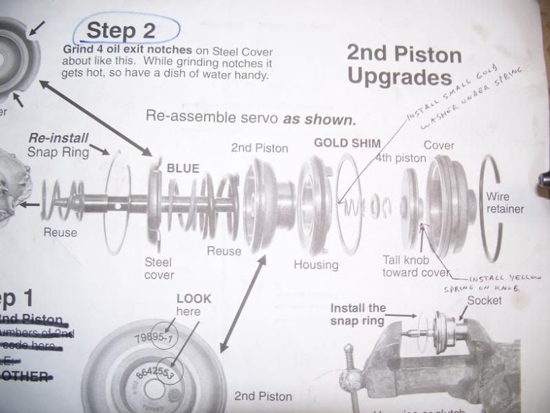
10. Transgo shift kit instructions.

11. From the top.

12. From the side.

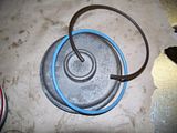
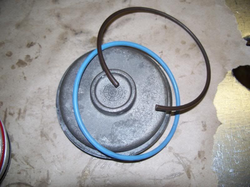
13. New (blue) SERVO cover o-ring (DO NOT install until AFTER checking the 2-4 band for sufficient wiggle room). Install dry with wire snap ring (black) and check for play.
14. Instructions on how to remove the servo snap ring in a vice.

15. More of the directions.

2. Modified servo cushion spring retainer (#15). Used a large silicone carbide bit on my dremel (the flat circular grinding one included in the grinding accessory kit - its not the cone green one, but the other one) at setting 9. The holes are to allow more oil to exit.

3. Another picture of this modification.
4. From the top.

5. Blow-up of 2-4 servo assembly. I forgot to put install yellow coated (may look all black if yellow marking rubbed off) spring over the tall **** of #25 (on the same side as where the arrow points for the large gold spacer).

6. Reassembled with new seals, spring installed, new large gold spacer and small gold washer. The red seal will not fill the entire groove - the stock seal did not fill the groove entirely either - I'm guessing its normal.
7. Another picture of it assembled. See the new black seals, large gold spacer, and circlip (like found on brake caliper pin) installed?

8. Close-up. Install the yellow (or entirely black spring if the yellow markings rubbed off) spring on the right side of the final piece you see in this picture before the servo cover. The spring will fit snugly over the **** and that's how you'll know its the right spring.
9. Ditto.
10. Transgo shift kit instructions.
11. From the top.
12. From the side.
13. New (blue) SERVO cover o-ring (DO NOT install until AFTER checking the 2-4 band for sufficient wiggle room). Install dry with wire snap ring (black) and check for play.
14. Instructions on how to remove the servo snap ring in a vice.
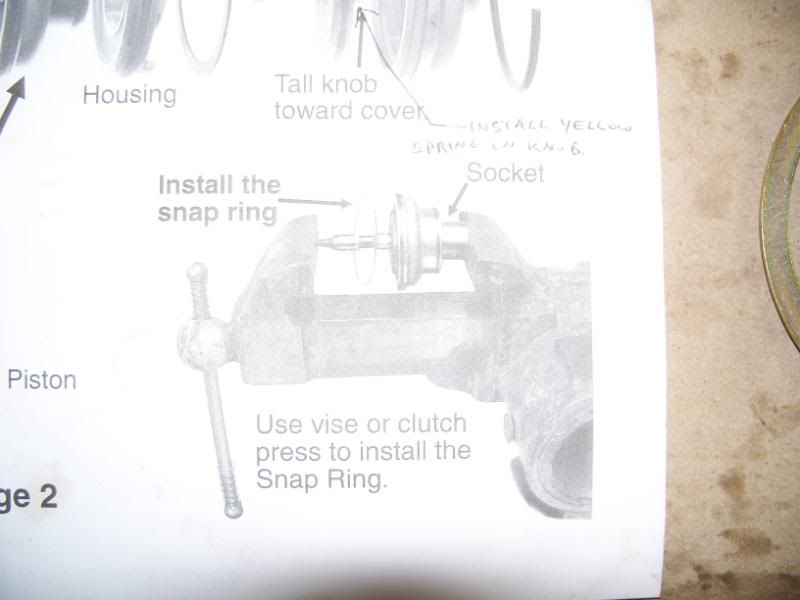
15. More of the directions.
Last edited by janarvae; 06-23-2008 at 12:14 AM. Reason: misinformation - not governor cover, servo cover