Fuel Injection
 04-18-2008, 08:08 AM
#41
Race Director

Member Since: Feb 2007
Location: northern california
Posts: 13,613
Received 6,529 Likes
on
3,004 Posts
C2 of Year Finalist (track prepared) 2019

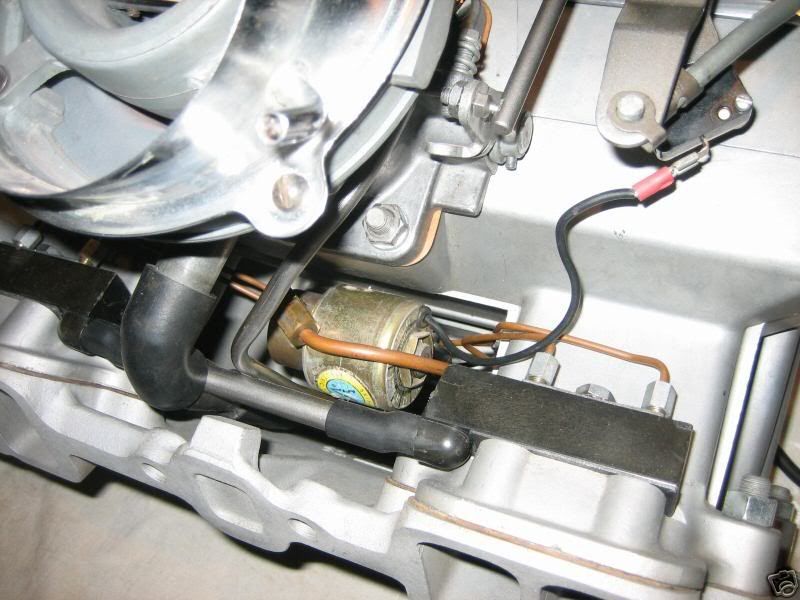
What you've got appears to be a '64-'65 unit. If so, the solenoid valve in the picture is not for anti-siphon protection; rather it provides a bypass path for fuel to reach the nozzles during engine cranking.
My guess is there is no anti-siphon solenoid valve and that the only siphoning protection is a small check valve that is (1) integral to the unit (2) in only one of the two siphoning fuel paths and (3) tends to fail.
If that were my unit, I'd replumb the fuel path to provide positive siphoning protection like I described in my earlier posting.
Good luck,
Jim
 04-18-2008, 08:36 AM
#42
Le Mans Master


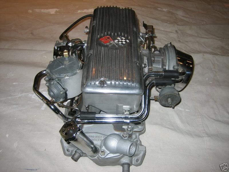
Matt, you've posted photos of a '63 7375 series FI unit with a modified starting circuit. Instead of a Cranking Signal Valve, your unit now uses a solenoid controlled by-pass around the fuel meter to provide nozzle fuel pressure during cranking.
For this modified starting circuit to work, you'll have to connect one solenoid lead to a terminal with 12 volts only during engine cranking. This same lead will also require a switch that can be used to disconnect the solenoid during engine re-starts. (Otherwise your engine might flood during hot re-starts.) I believe you already have such a switch mounted on the bellcrank boss.
This unit originally came with an anti-siphon "pill" valve inside the fuel meter. It also came with a spring-loaded anti-siphon needle valve in the spider hub. I can not tell if either of these is still present and working, however.
My own experiments with installing anti-siphon solenoids in the '63 - '65 fuel meter-to-spider tubing have been disappointing. Regardless of where it is placed in this tubing, a standard solenoid valve causes a flow restriction in this particular application that changes the fuel supply curve. In my experiments, this change has been significant. However, if you can find a solenoid valve that is full opening (like a tiny gate or ball valve) with no flow restriction when open, I can see how it could be installed in the short feed line without affecting calibration.
Regards,
Jerry
Last edited by jerrybramlett; 04-18-2008 at 11:13 AM.
04-20-2008, 11:04 AM
#43
Racer

Thread Starter
Matt, you've posted photos of a '63 7375 series FI unit with a modified starting circuit. Instead of a Cranking Signal Valve, your unit now uses a solenoid controlled by-pass around the fuel meter to provide nozzle fuel pressure during cranking.
For this modified starting circuit to work, you'll have to connect one solenoid lead to a terminal with 12 volts only during engine cranking. This same lead will also require a switch that can be used to disconnect the solenoid during engine re-starts. (Otherwise your engine might flood during hot re-starts.) I believe you already have such a switch mounted on the bellcrank boss.
This unit originally came with an anti-siphon "pill" valve inside the fuel meter. It also came with a spring-loaded anti-siphon needle valve in the spider hub. I can not tell if either of these is still present and working, however.
My own experiments with installing anti-siphon solenoids in the '63 - '65 fuel meter-to-spider tubing have been disappointing. Regardless of where it is placed in this tubing, a standard solenoid valve causes a flow restriction in this particular application that changes the fuel supply curve. In my experiments, this change has been significant. However, if you can find a solenoid valve that is full opening (like a tiny gate or ball valve) with no flow restriction when open, I can see how it could be installed in the short feed line without affecting calibration.
Regards,
Jerry
For this modified starting circuit to work, you'll have to connect one solenoid lead to a terminal with 12 volts only during engine cranking. This same lead will also require a switch that can be used to disconnect the solenoid during engine re-starts. (Otherwise your engine might flood during hot re-starts.) I believe you already have such a switch mounted on the bellcrank boss.
This unit originally came with an anti-siphon "pill" valve inside the fuel meter. It also came with a spring-loaded anti-siphon needle valve in the spider hub. I can not tell if either of these is still present and working, however.
My own experiments with installing anti-siphon solenoids in the '63 - '65 fuel meter-to-spider tubing have been disappointing. Regardless of where it is placed in this tubing, a standard solenoid valve causes a flow restriction in this particular application that changes the fuel supply curve. In my experiments, this change has been significant. However, if you can find a solenoid valve that is full opening (like a tiny gate or ball valve) with no flow restriction when open, I can see how it could be installed in the short feed line without affecting calibration.
Regards,
Jerry
i will look into that wiring as you described
04-27-2008, 11:34 AM
#44
Racer
Thread Starter
i checked my vacumm today, off the carb going to dist, and my guage bounces for 8-15 vacumm, is this possiable or is this an issue
would that be too low for the fuelie unit?
thanks
would that be too low for the fuelie unit?
thanks
04-27-2008, 02:49 PM
#45
Le Mans Master
A manifold vacuum reading that varies from 8" to 15" at an 800 rpm idle speed indicates a serious mechanical problem. Please find another source point to measure and recheck this reading.
There is a write-up on my website in the "Tech Tips" section that discusses camshaft selection for fuel injected engines.
04-27-2008, 03:38 PM
#46
Team Owner

Member Since: Oct 2004
Location: Springfield MO
Posts: 23,831
Likes: 0
Received 6 Likes
on
6 Posts
St. Jude Donor '07

Back to the regularly-scheduled mechanical FI discussion.
 04-27-2008, 08:51 PM
#47
Racer
Thread Starter
hey all Mr. Stupid here!!! 
i tried another vacuum guage and guess what, i have 12 of vacuum!! at 800 idle
the other guage that i was using was no good, so i guess i should be good for my fuelie setup
thanks
i tried another vacuum guage and guess what, i have 12 of vacuum!! at 800 idle
the other guage that i was using was no good, so i guess i should be good for my fuelie setup
thanks